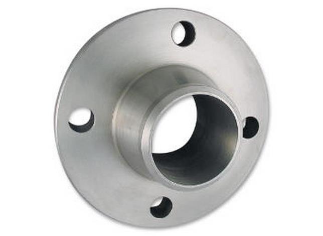
Series A Weldneck MSS-SP-44
- In accordance to ASME/ANSI B16.5, MSS SP-6 & 25
- ASTM / ASME A/SA-182
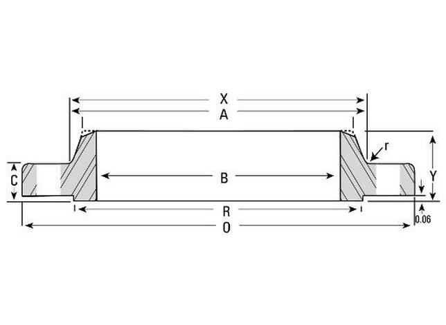
- Bore B is to be specified by purchaser.
Additional Information
Use Custom Product to make a request for dimensions not shown.
Necks are furnished machined all over.
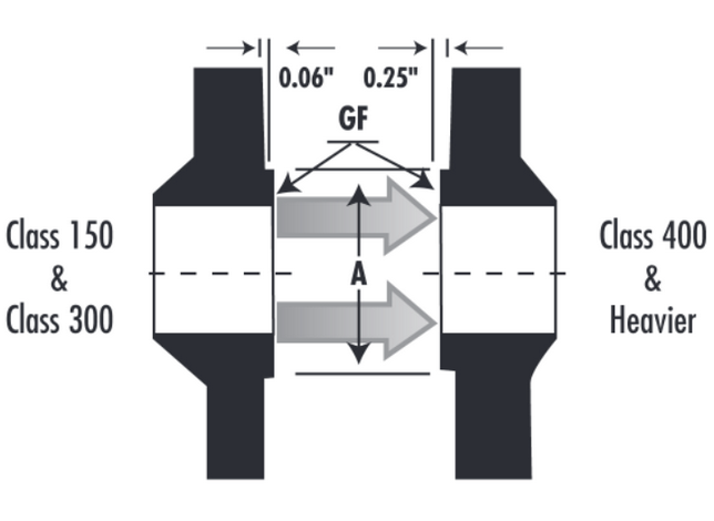
Unless otherwise specified, Class 300 Seamless Long Weld Necks will be furnished drilled and with a 0.06” raised face which is included in thickness “C” and Length “Y”.
Pressure-Temperature Ratings for Plant Piping and Pressure Vessel Flanges (Class 300)
| Metal Temperature F° | Pressureb (Pounds per Square Inch Gage) |
|---|---|
| 100 | 740 |
| 200 | 675 |
| 300 | 655 |
| 400 | 635 |
| 500 | 600 |
| 600 | 550 |
| 650 | 535 |
| 700 | 535 |
| 750 | 505 |
| 800 | 410 |
| 850 | 270 |
| 900 | 170 |
| 950 | 105 |
| 1000c | 50 |
a Based on the pressure ratings in ANSI B16.5 (1977), for use with flanges designed in accordance with the ASME Code or ANSI B31.1.
b Pressure-temperature ratings are based on material specifications ASTM A105 and A216 Grade WCB. Limitations on the use of these materials shall be in accordance with the applicable code.
c Maximum service temperature for the current class.
Dimensional Tolerances
| OUTSIDE DIAMETER* | When O.D. is 24” or less | ±1/16” |
| When O.D. is over 24” | ±1/8” | |
| INSIDE DIAMETER* | 10” and smaller | ±1/32” |
| 12” through 18” | ±1/16” | |
| 20” and larger | +1/8” -1/16” | |
| DIAMETER OF CONTACT FACE | 1/16” Raised Face | ±1/32” |
| 1/4” raised Face Tongue and Groove, or Male and Female | ±1/64” | |
| DIAMETER OF HUB AT POINT OF WELDING | 5” and smaller | +3/32”, -1/32” |
| 6” and larger | +5/32”, – 1/32” | |
| WELDING BEVEL STANDARDS | See drawings | |
| DIAMETER OF HUB AT BASE* | When Hub Base is 24” or less | ±1/16” |
| When Hub Base is over 24” | ±1/8” | |
| DRILLING | Bolt Circle | ±1/16” |
| Bolt hole spacing | ±1/32” | |
| ECCENTRICITY BOLT CIRCLE & FACING (with respect to Bore*) | 2 1/2” and smaller | 1/32” max |
| 3” and larger | 1/16” max | |
| LENGTH THRU HUB* | 10” and smaller | ±1/16” |
| 12” and larger | ±1/8” | |
| THICKNESS | 18” and smaller | +1/8” -0” |
| 20” and larger | +3/16” -0” | |
Back to top