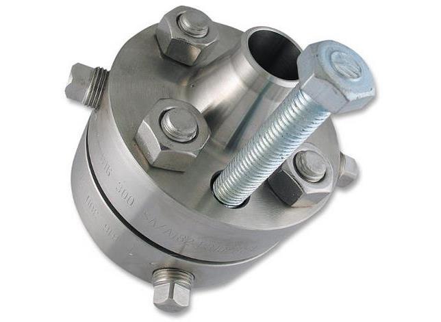
Orifice Weldneck
- In accordance to ASME/ANSI B16.5, MSS SP-6 & 25
- ASTM / ASME A/SA-182
Additional Information
Use Custom Product to make a request for dimensions not shown.
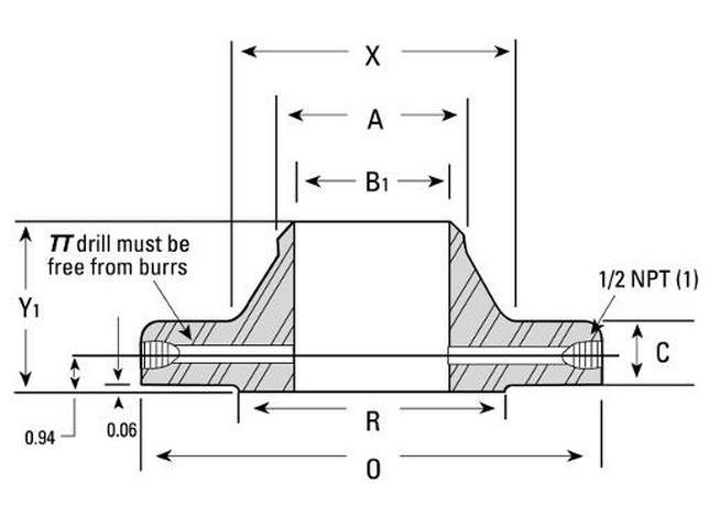
1. NOTES: Other NPT sizes may be furnished if required.
2. Weld neck flanges NPS 3 and smaller are identical to Class 600 flanges and may be so marked.
3. All other dimensions are in accordance with ASME/ANSI B16.5
4. Bolt lengths include allowance for orifice and gasket thickness of 0.25 in. for NPS 1-12 and 0.38 in. for NPS 14-24.
5. In conformance with ASME/ANSI B16.5, stud bolt lengths do not include point heights.
6. Bore diameter of weld neck flanges (B1) is to be specified by the purchaser.
Pressure-Temperature Ratings (Class 300)
| Metal Temperature F° | Pressurea (Type 304/L & 316/L) |
|---|---|
| -20 à 100 | 600 |
| 200 | 505 |
| 300 | 455 |
| 400 | 415 |
| 500 | 380 |
| 600 | 360 |
| 650 | 350 |
| 700 | 345 |
| 750 | 335 |
| 800 | 330 |
| 850 | 320b |
| 900 | – |
| 950 | – |
| 1000 | – |
a (Pounds per Square Inch Gage)
b Class 316/L
Dimensional Tolerances
| OUTSIDE DIAMETER* | When O.D. is 24” or less | ±1/16” |
| When O.D. is over 24” | ±1/8” | |
| INSIDE DIAMETER* | 10” and smaller | ±1/32” |
| 12” through 18” | ±1/16” | |
| 20” and larger | +1/8” -1/16” | |
| DIAMETER OF CONTACT FACE | 1/16” Raised Face | ±1/32” |
| 1/4” raised Face Tongue and Groove, or Male and Female | ±1/64” | |
| DIAMETER OF HUB AT POINT OF WELDING | 5” and smaller | +3/32”, -1/32” |
| 6” and larger | +5/32”, – 1/32” | |
| WELDING BEVEL STANDARDS | See drawings | |
| DIAMETER OF HUB AT BASE* | When Hub Base is 24” or less | ±1/16” |
| When Hub Base is over 24” | ±1/8” | |
| DRILLING | Bolt Circle | ±1/16” |
| Bolt hole spacing | ±1/32” | |
| ECCENTRICITY BOLT CIRCLE & FACING (with respect to Bore*) | 2 1/2” and smaller | 1/32” max |
| 3” and larger | 1/16” max | |
| LENGTH THRU HUB* | 10” and smaller | ±1/16” |
| 12” and larger | ±1/8” | |
| THICKNESS | 18” and smaller | +1/8” -0” |
| 20” and larger | +3/16” -0” | |
Back to top