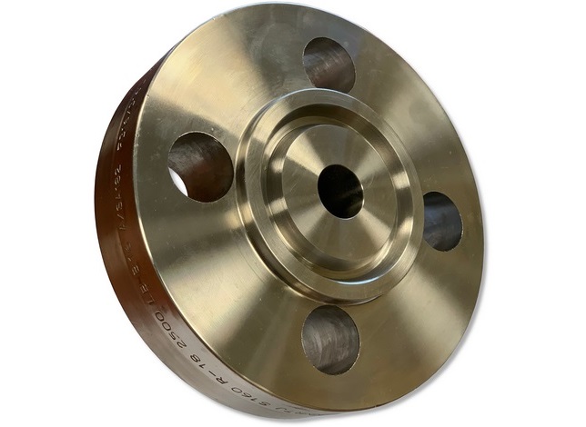
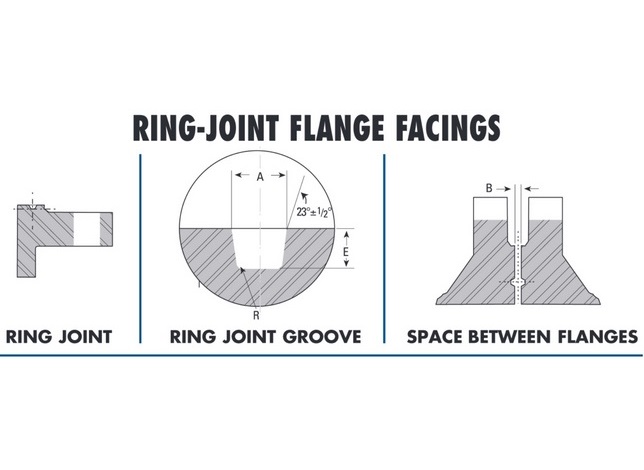
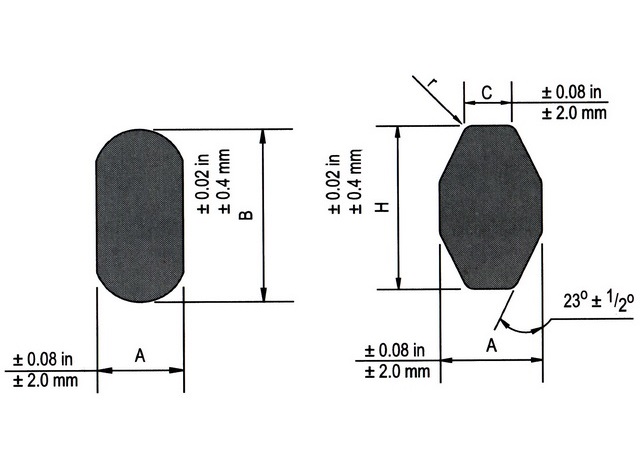
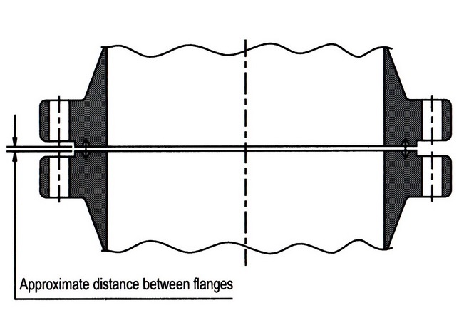
Ring Type Joint Weldneck
- In accordance to ASME/ANSI B16.5, MSS SP-6 & 25
- ASTM / ASME A/SA-182
- Necks are furnished machined all over.
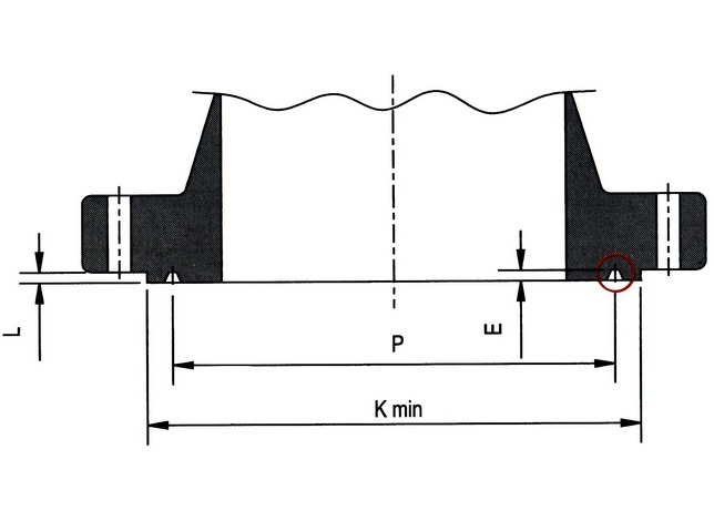
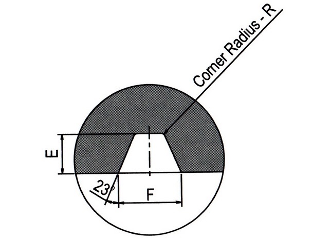
- The depth of groove is added to the minimum flange thickness
- * Raised Face “L” is equal to groove dimension “E” but is not subject to tolerance for “E”
- Unless otherwise specified, Class 600 Seamless Long Weld Necks will be furnished drilled and with a 0.06” raised face which is included in thickness “Q” and Length “Y”
Additional Information
Use Custom Product to make a request for dimensions not shown.
Pressure-Temperature Ratings (Class 600)
| Metal Temperature F° | Pressurea (Type 304/L & 316/L) |
|---|---|
| -20 à 100 | 1200 |
| 200 | 1015 |
| 300 | 910 |
| 400 | 825 |
| 500 | 765 |
| 600 | 720 |
| 650 | 700 |
| 700 | 685 |
| 750 | 670 |
| 800 | 660 |
| 850 | 645b |
| 900 | – |
| 950 | – |
| 1000 | – |
a (Pounds per Square Inch Gage)
b Class 316/L
Dimensional Tolerances
| OUTSIDE DIAMETER* | When O.D. is 24” or less | ±1/16” |
| When O.D. is over 24” | ±1/8” | |
| INSIDE DIAMETER* | 10” and smaller | ±1/32” |
| 12” through 18” | ±1/16” | |
| 20” and larger | +1/8” -1/16” | |
| DIAMETER OF CONTACT FACE | 1/16” Raised Face | ±1/32” |
| 1/4” raised Face Tongue and Groove, or Male and Female | ±1/64” | |
| DIAMETER OF HUB AT POINT OF WELDING | 5” and smaller | +3/32”, -1/32” |
| 6” and larger | +5/32”, – 1/32” | |
| WELDING BEVEL STANDARDS | See drawings | |
| DIAMETER OF HUB AT BASE* | When Hub Base is 24” or less | ±1/16” |
| When Hub Base is over 24” | ±1/8” | |
| DRILLING | Bolt Circle | ±1/16” |
| Bolt hole spacing | ±1/32” | |
| ECCENTRICITY BOLT CIRCLE & FACING (with respect to Bore*) | 2 1/2” and smaller | 1/32” max |
| 3” and larger | 1/16” max | |
| LENGTH THRU HUB* | 10” and smaller | ±1/16” |
| 12” and larger | ±1/8” | |
| THICKNESS | 18” and smaller | +1/8” -0” |
| 20” and larger | +3/16” -0” | |
Back to top