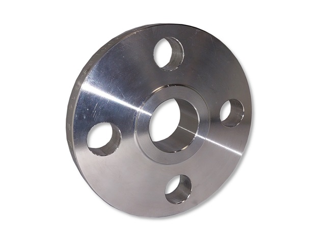
Slip-on
- Please change the NPS, Grade and other options to filter the Product Dimension Chart below.
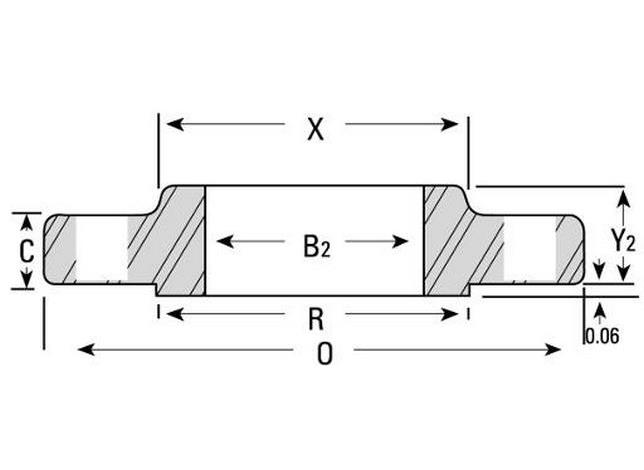
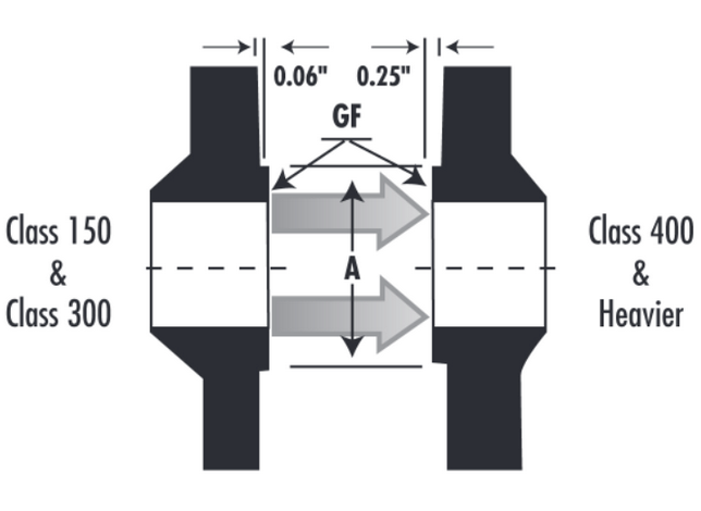
- Refer to the other images for the detailed dimensions.
- Click here to see the full flange bolt-up chart.
- Length measurements are given in inches, unless stated otherwise.
- In accordance to ASME/ANSI B16.5, MSS SP-6 & 25
- ASTM / ASME A/SA-182
Additional Information
Use Custom Product to make a request for dimensions not shown.
Pressure-Temperature Ratings (Class 300)
| Metal Temperature F° | Pressurea (Type 304/L & 316/L) |
|---|---|
| -20 à 100 | 600 |
| 200 | 505 |
| 300 | 455 |
| 400 | 415 |
| 500 | 380 |
| 600 | 360 |
| 650 | 350 |
| 700 | 345 |
| 750 | 335 |
| 800 | 330 |
| 850 | 320 |
| 900 | – |
| 950 | – |
| 1000 | – |
a (Pounds per Square Inch Gage)
b Class 316/L
Dimensional Tolerances
| OUTSIDE DIAMETER* | When O.D. is 24″ or less | ±1/16″ |
| When O.D. is over 24″ | ±1/8″ | |
| INSIDE DIAMETER* | Threaded | Within limits on boring gauge |
| Slip-On, and Lap Joint 10″ and smaller | +1/32″ | |
| 12″ and smaller | +1/16″ | |
| DIAMETER OF COUNTERBORE | Same as for Inside Diameter | |
| DIAMETER OF CONTACT FACE | 1/16″ Raised Face | ±1/32″ |
| 1/4″ Raised Face Tongue and Groove, or Male and Female | ±1/64″ | |
| OUTSIDE DIAMETER OF HUB* | 12″ and smaller | +3/32″, -1/16″ |
| 14″ and larger | ±1/8″ | |
| DRILLING | Bolt Circle | ±1/16″ |
| Bolt hole spacing | ±1/32″ | |
| ECCENTRICITY BOLT CIRCLE & FACING (with respect to Bore*) | 2 1/2″ and smaller | 1/32″ max |
| 3″ and larger | 1/16″ max | |
| LENGTH THRU HUB* | 18″ and smaller | +1/8″ -1/32″ |
| 20″ and larger | +3/16″ -1/16″ | |
| THICKNESS | 18″ and smaller | + 1/8″ -0″ |
| 20″ and larger | +3/16″ -0″ | |
Back to top